
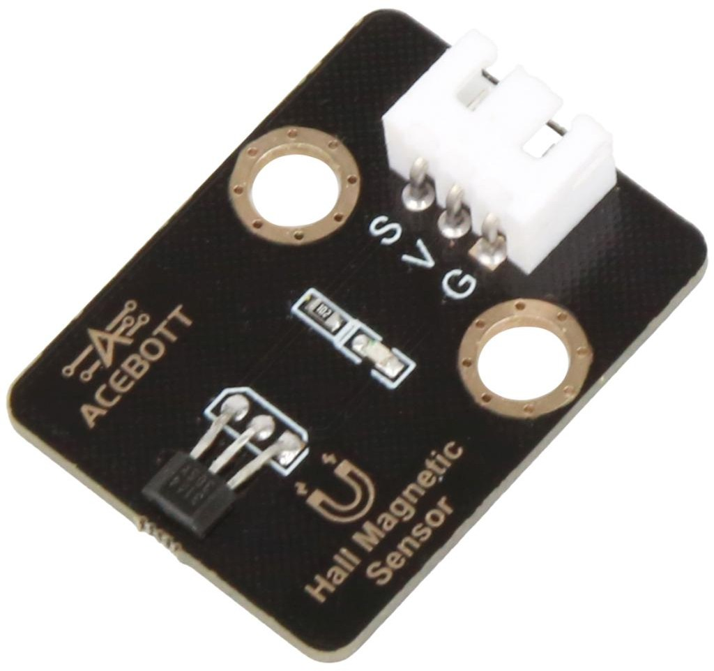
Product Introduction #
The Hall sensor is a magnetic-sensitive sensor based on the Hall effect, mainly used to detect changes in the magnetic field and convert them into electrical signals for output.
The core principle is that when current passes through a conductor, if there is a magnetic field perpendicular to the direction of the current, an electric potential difference (Hall voltage) will be generated on both sides of the conductor. By measuring this voltage, the strength or position change of the magnetic field can be reflected.
Application reference: Motor speed measurement, valve opening and closing status monitoring, proximity switch, magnetic encoder, etc. scenarios.
Parameter Specification #
| Parameters | Value/Description |
|---|---|
| Operating voltage | 3.3V~5V |
| Operating temperature | -10°C~+50°C |
| Output signal | Digital signal |
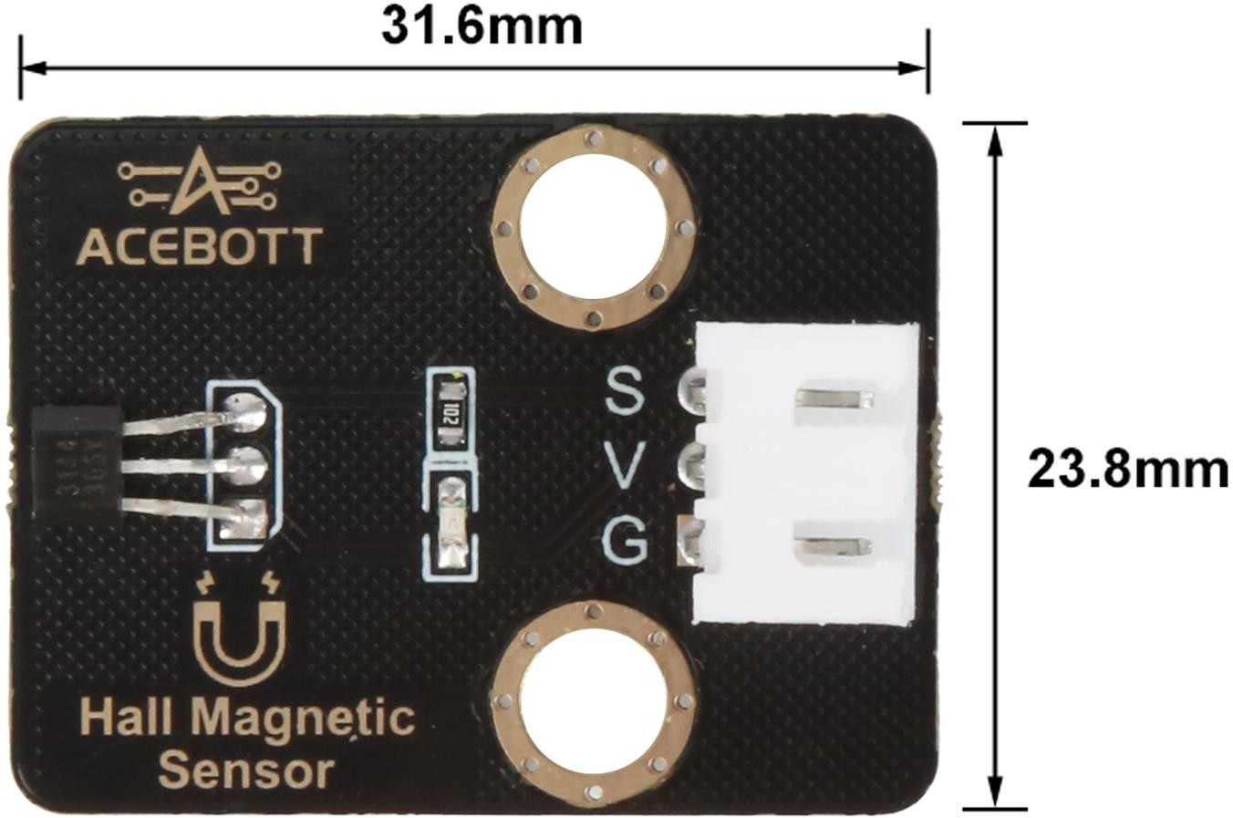
| Size | 3.16cm*2.38cm |
Wiring Diagram #
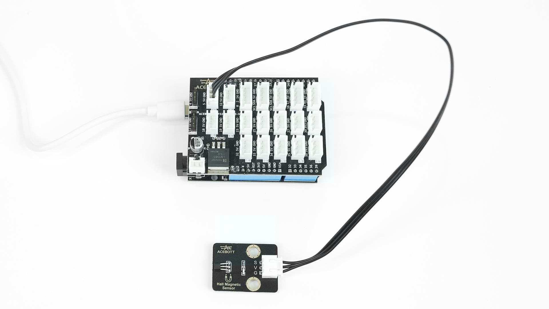
Note:Expansion board is attached to esp32 controller board.
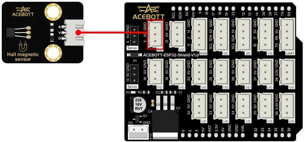
| Hall Sensor | ESP32 |
|---|---|
| VCC | 5V |
| GND | GND |
| Sign | Pin 5 |
Sample Code #
void loop() {
int state = digitalRead(HALL_PIN);
#define HALL_PIN 5 // Digital Hall sensor output pin void setup() {
Serial.begin(115200); pinMode(HALL_PIN, INPUT);
}


Serial.println(state); // Magnet near Hall delay(200);
}
Test Results #
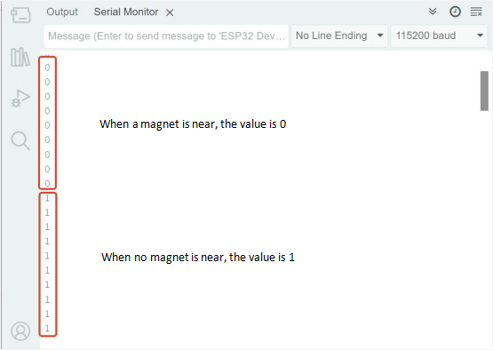
After uploading the code to the controller board, open the serial port monitor of the Arduino IDE, set the baud rate to 115200, and switch to the scroll mode.
When we bring a magnet close to the sensor, we will find that the serial port will print the sensor values in real time.
Related Resources #
PDF and Code


