Product Introduction #
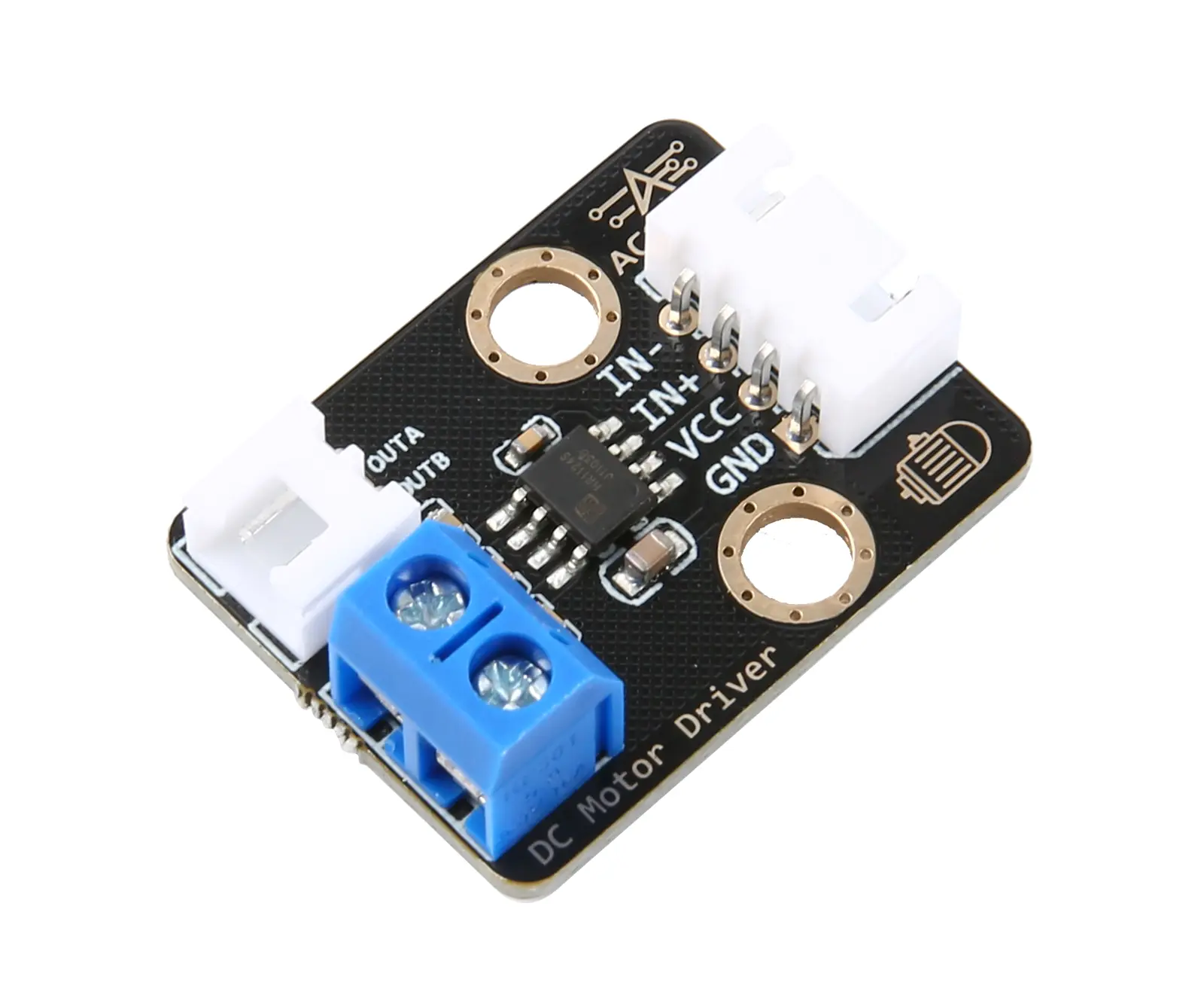
The DC Motor Driver Module is an electronic component that controls the DC motor, which controls the rotation direction and speed of the motor by controlling the input signal. There are two control pins on the drive module, one to control clockwise rotation (IN +) and the other to control counterclockwise rotation (IN-). By applying different level signals (high or low levels) to these pins, the motor has clockwise rotation and counterclockwise rotation that can be achieved.
Application reference: small robots, intelligent cars, fans and other projects.
Parameter Specification #
| Parameter | Value/Description |
| Operating voltage | 3.3V-5V |
| Output current | 200mA |
| Operating temperature | -10°C~+50°C |
| Size | 3.2cm*2.4cm |

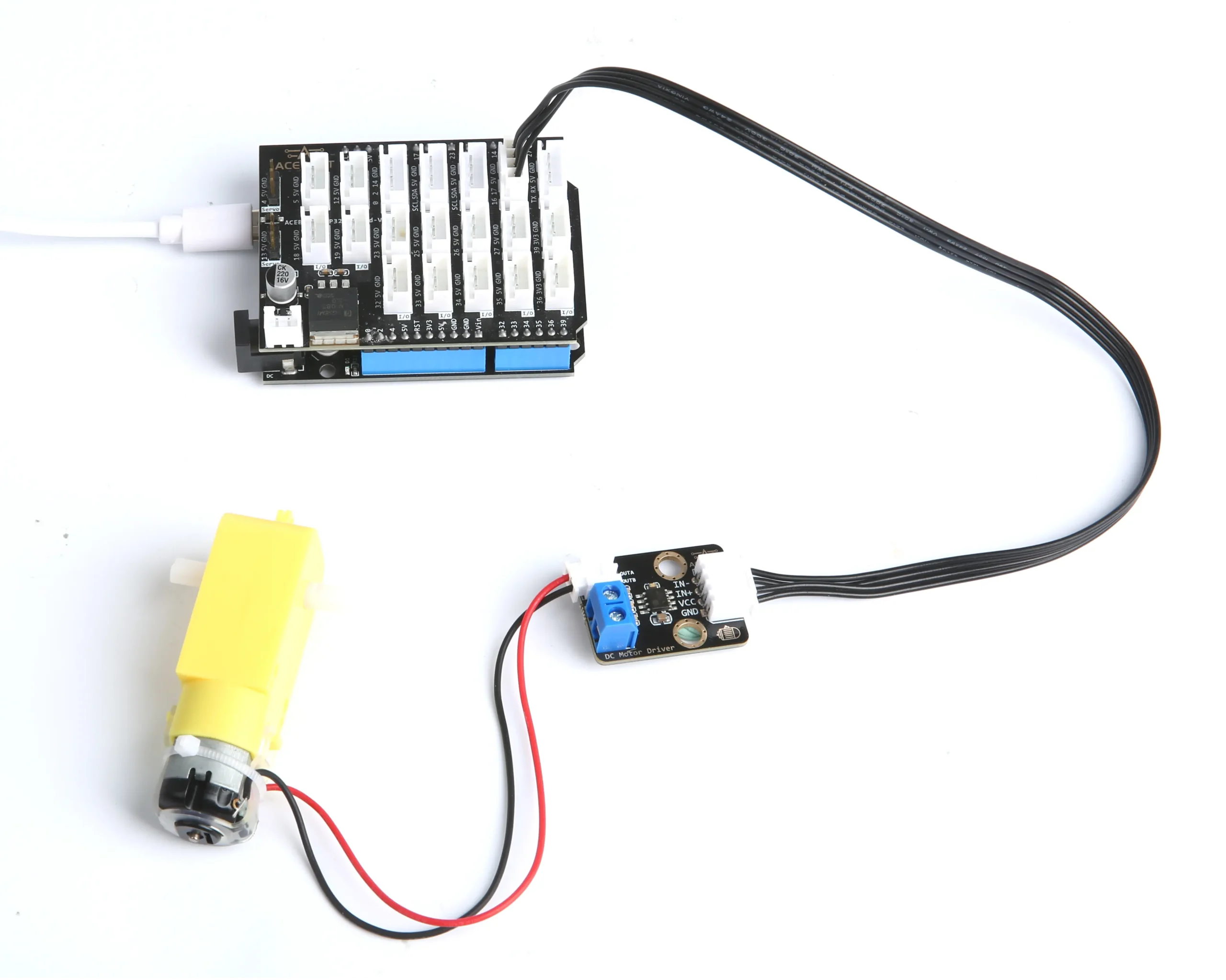
Wiring Diagram #
Note: Expansion board is attached to esp32 controller board.
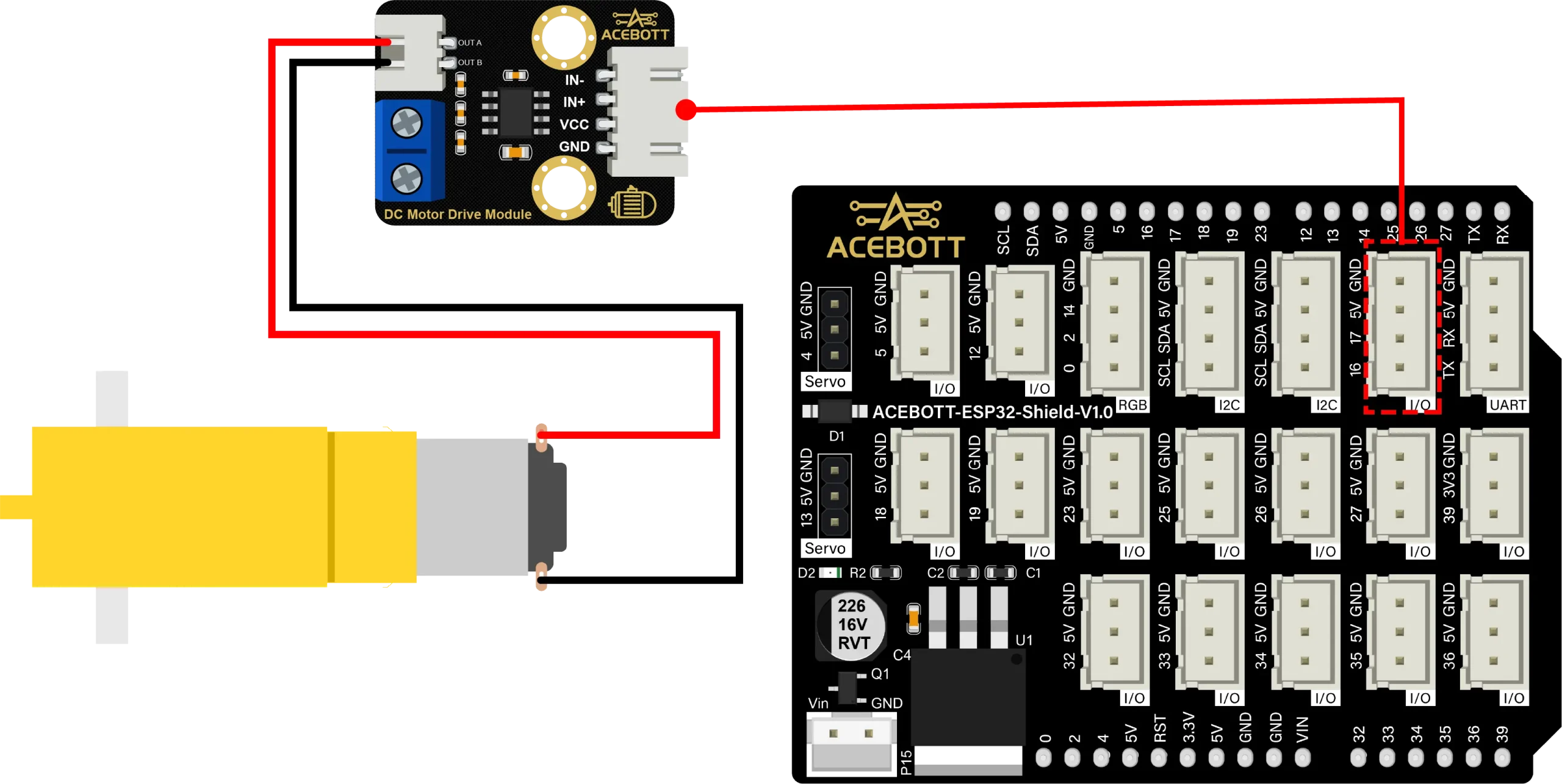
| DC Motor Driver Module | ESP32 |
| IN- | Digital Pin 16 |
| IN+ | Digital Pin 17 |
| VCC | 5V |
| GND | GND |
Sample Code #
void setup(){
pinMode(17, OUTPUT);//Set pin 17 to output mode
pinMode(16, OUTPUT);//Set pin 16 to output mode
}

void loop(){
digitalWrite(17,HIGH);
digitalWrite(16,LOW);//Motor clockwise rotation
delay(1000);
digitalWrite(17,LOW);
digitalWrite(16,LOW);//Motor stop
delay(1000);
digitalWrite(17,LOW);
digitalWrite(16,HIGH);//Motor contrarotate
delay(1000);
digitalWrite(17,LOW);
digitalWrite(16,LOW);//Motor stop
delay(1000);
}
Note: If you are using an Arduino board, then change the IN- pin in the program to PIN3, IN+ pin in the program to PIN5, and then connect the hardware pin to PIN3, PIN5 and upload the program.
Test Result #
When you successfully connect the line according to the wiring diagram and successfully upload the correct program, the motor cycle can turn clockwise for 1 second, stop for 1 second, then turn counterclockwise for 1 second, and stop for 1 second.
Related Resources #
Get Quotation or Buy From #
B2B Business: info@acebott.com


