
 Introduction #
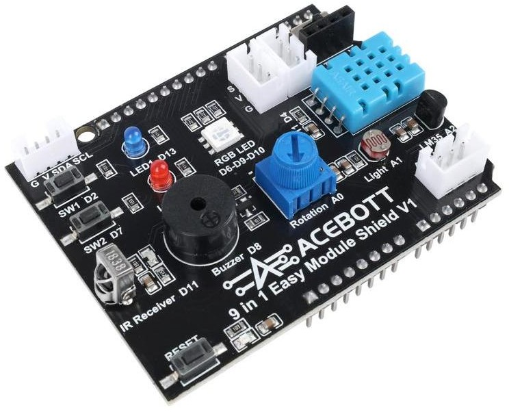
The 9-in-1 Easy Module Shield is an integrated functional board that conforms to the Arduino UNO physical interface standard. In this tutorial, we will insert the ESP32 Plus controller board under the 9-in-1 Easy Module Shield expansion board to form a complete
The 9-in-1 Easy Module Shield integrates a variety of commonly used input and output devices and expansion interfaces, eliminating the need for soldering and complex wiring, greatly lowering the barrier to entry for beginners to conduct hardware experiments. Connecting it is equivalent to equipping the control system with multiple “sensory organs” and “action organs” at once.
Features #
- Compatible with controller board such as ESP32 Plus board,UNO R3 and MEGA2560.
- Comes with 2 LED indicators to show the program status.
- Comes with 2 switches for external interrupt experiment.
- Comes with a reset button
- Comes with DHT11 sensor for measuring temperature and humidity.
- Comes with a potentiometer for analog input
- Comes with a passive buzzer for alarm.
- Comes with a full-color RGB LED
- Comes with a photocell to detect the brightness of light
- Comes with LM35D temperature sensor
- Comes with an infrared receiver
- 2digital pins(D3 and D5)
- 1 analog pin(A3)
- One IIC interface
- One TTL serial pin
Specifications #
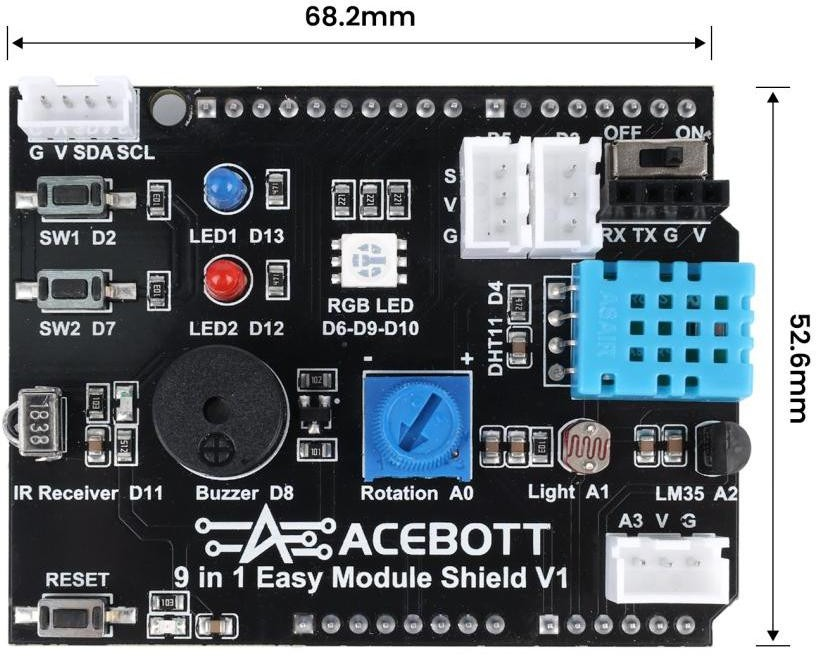
Size: 68.2mm * 52.6mm
Weight: 21g
Note:
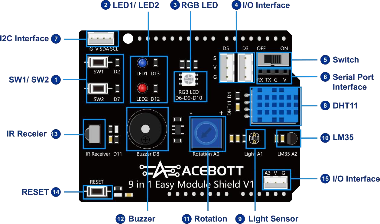
(1)The onboard modules on the 9-in-1 Easy Module Shield are shown in the table below:
| Module Name | Onboard Pins | ESP32 pins | Function Description |
|---|---|---|---|
| SW1/SW2 | D2/D7 | GPIO26/14 | Two independent buttons for human-machine interaction input, supporting experiments such as switch control and interrupt triggering. |
| LED1/LED2 | D13/D12 | GPIO18/19 | Blue and red LEDs for status indication, such as breathing lights and status indicators |
| RGB LED | D6-D9-D10 | GPIO27-13-5 | Full-color LED, which can display various colors by mixing red, green, and blue light |
| I/O Interface | D3/D5 | GPIO25/16 | Reserved digital I/O ports, supporting PWM output, which can be connected to servo motors, relays, and other modules. |
| Switch | / | / | Toggle switch connects or disconnects the sensor connected to the serial port from the controller board. |
| Serial Port Interface | Rx-Tx | Rx0-Tx0 | Used to connect external serial port devices such as cameras, voice modules, and serial screens. |
| I2C Interface | SDA-SCL | SDA-SCL | IIC interface, used to connect OLED displays, RTC clock modules, and other I2C devices. |
| DHT11 | D4 | GPIO17 | Digital temperature and humidity sensor, used to detect ambient temperature and humidity. |
| Light Sensor | A1 | GPIO4 | Analog ambient light intensity sensor, its resistance value changes with light, and can be used to make light control devices. |
| LM35 | A2 | GPIO35 | Analog precision temperature sensor, the output voltage is proportional to the Celsius temperature, used to measure ambient temperature. |
| Rotation | A0 | GPIO2 | Adjustable resistor, rotating the knob changes the output voltage, commonly used for voltage adjustment, parameter setting, etc. |
| Buzzer | D8 | GPIO12 | It can be controlled to emit sound by outputting a PWM signal, used to create alarms or play simple music. |
| IR Receiver | D11 | GPIO23 | Receives infrared remote control signals, can be used for remote control of lights, etc. |
| RESET | / | / | Used to reset the microcontroller system |
| I/O Interface | A3 | GPIO34 | Reserved analog I/O ports, which can be connected to potentiometers, analog light sensors, etc.; these ports can also be used as digital I/O ports. |
(2)On the side of the ESP32 Plus controller board, you can see the correspondence between the 9-in-1 onboard interface and the ESP32 GPIO interface. You can check it yourself.
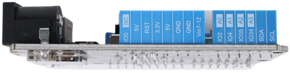
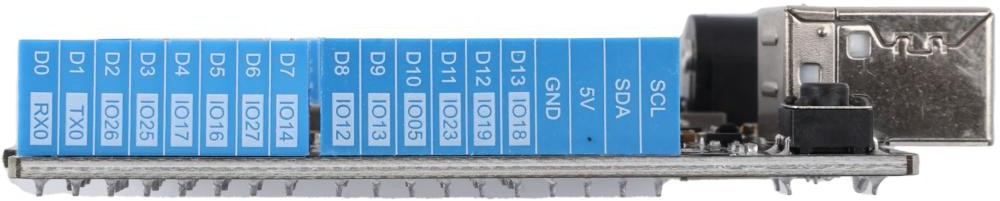
(3) Key Tips for Using the Serial Port: The Serial Port Interface shares a pin (UART0) with the controller board’s program download port. Switch the function using the serial port selection switch.
“OFF” side: Connect to the computer’s USB port for program upload and serial port monitoring. Before downloading the program, please ensure that the switch is in this position and disconnect the external serial port device.
“ON” Side: Connected to the Serial Port Interface on the expansion board, allowing communication with external serial devices. Program download via USB is not possible in this position.
4.Sample Program #
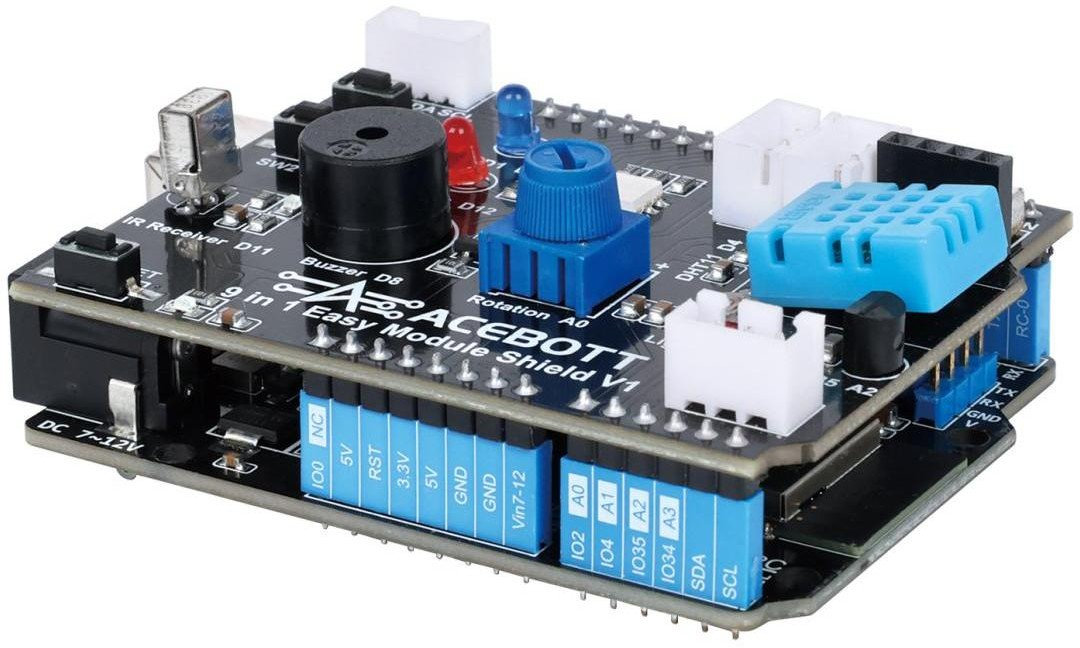
Connect the expansion board to the esp32 Plus controller board. Connect the controller board to the computer using a USB type-B data cable. Upload the program to control the turning on and off of the LED lights.
(1)Wiring diagram #
(2) Program #
#define Led 19
void setup(){
    pinMode(Led, OUTPUT);//Define the mode of the LED
}
void loop(){
    digitalWrite(Led,HIGH);//Turn on the LED
    delay(1000);
    digitalWrite(Led,LOW);//Turn off the LED
    delay(1000);
}
5.Program Effect #
After the program is uploaded, the LED will flash once every second.
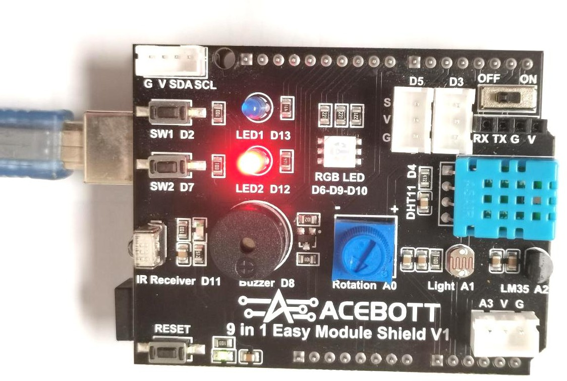
Notes: To ensure that the written program can be successfully uploaded to the ESP32 Plus controller board, please check the following before each program upload.
(1)Switch the serial port selection switch on the expansion board to the OFF side. If it is on the ON side and an external device is connected to the serial port, the serial port will be switched to the external interface, causing the computer to be unable to recognize the device.
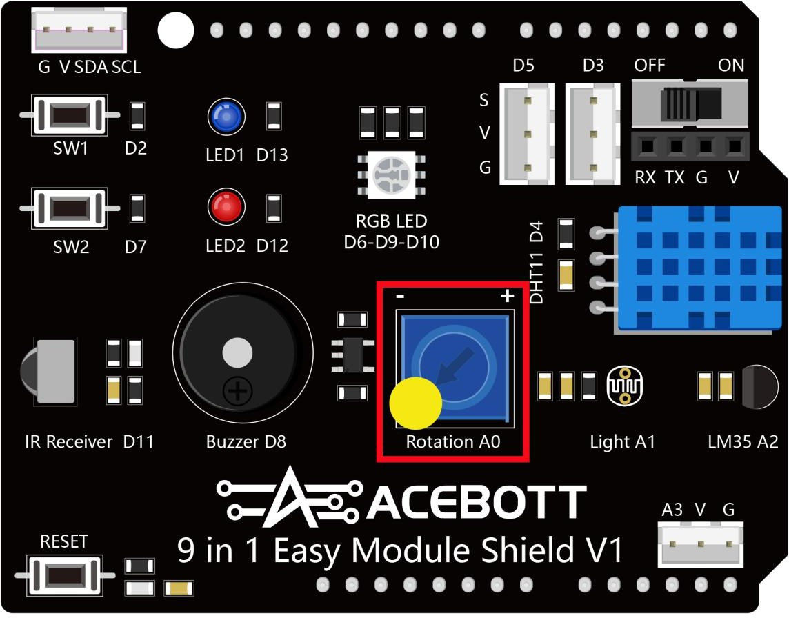
(2)Set the potentiometer knob/switch on the expansion board to the far left (marked by the yellow circle in the image below). This potentiometer circuit is connected to the A0 (GPIO2) pin on the controller board. GPIO2 is the Strapping pin of the ESP32. It must be low when powered on to enter download mode. If the regulator is not on the left, it will be pulled high, causing the chip to fail to respond to upload requests. This is one of the most common reasons for upload failure.
(3)If the upload still fails after completing the above two steps, please remove the ESP32 Plus controller board from the 9-in-1 expansion board and connect the computer and the ESP32 Plus controller board separately using a USB cable to upload the program. After success, disconnect the USB cable first, and then plug the controller board back into the expansion board.


