
Introduction #
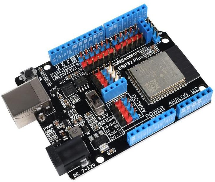
The ESP32 Plus board is a controller board that adopts the standard interface layout of Arduino UNO and is equipped with an ESP32 chip. Its physical structure is compatible with the UNO ecosystem expansion boards, but the core architecture is entirely based on ESP32 and has not undergone any modifications to the UNO board. This board serves as the “control core” in the programming control system, integrating a high-performance main control chip and functioning as the “brain” of the entire control system.
ESP32 Plus is equipped with a variety of peripheral interfaces, such as high-speed SDIO/SPI, UART, I2S and I2C. Additionally, it can be equipped with the FreeRTOS operating system, which is highly suitable for IoT and smart home solutions.
Features #
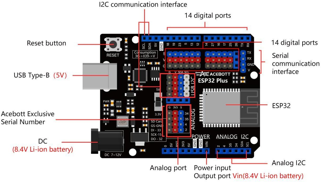
- USB Type-B port
- The pin interface is rich, to meet the needs of the work construction
- Foot color is clear, easy to distinguish and wiring
- Configure a switch for 3.3V and 5V power supply switching to enable the power supply to be changed at any time.
- Low power consumption, supporting multiple power-saving modes to meet the operation requirements of low-power devices.
- Supports microSD card storage expansion and has strong peripheral expansion capabilities.
- Built-in Wi-Fi and Bluetooth 4.2 module for wireless communication.
Specifications #
| Parameter | Value/Description |
|---|---|
| Chip | ESP-WROOM-32E |
| Clock | 240MHz |
| ROM | 448KB |
| SRAM | 520KB |
| FLASH | 4MB |
| Interface type | UART/I2C/SPI/CAN |
| Input Voltage | 8.4V Li-ion battery |
| Number of Pins | 25(DIGITAL)/15(ANALOG)/25(PWM)/2(DAC)/2(UART)/2(SPI)/1(I2C) |
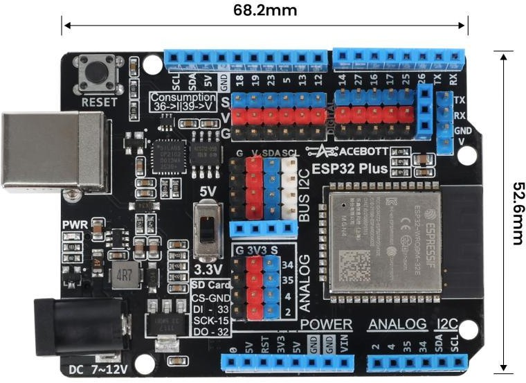
| size | 6.82cm*5.26cm |
Pin Description #
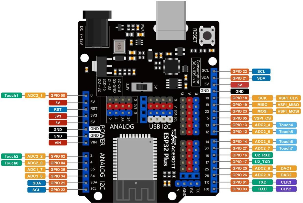 The figure illustrates the GPIO pins and the corresponding functions of the ESP32 Plus controller board, including ADC, DAC, PWM, I2C, SPI pins, etc.
- Only Input Pin: GPIO 34/GPIO 35/GPIO 36/GPIO 39
- Default I2C Pin: GPIO 21(SDA)/GPIO 22(SCL)
- DAC Pin: GPIO 25(DAC1)/GPIO 26(DAC2)
Note #
(1)The ADC2 pin cannot be used when using Wi-Fi. Therefore, if you can’t get the value from the ADC2 GPIO on Wi-Fi, consider using the ADC1 GPIO instead.
(2)The ADC input channel has 12-bit resolution. This means that you can get analog readings between 0 and 4095, where analog value 0 corresponds to 0V and analog value 4095 corresponds to 3.3V. You can also set the resolution of the channel as well as the ADC range on the code.
Configure the Development Environment of the Controller Board #
To use the ESP32 Plus controller board for programming, you need to install the programming software, serial port tools and related library files.
So, follow these steps to install it:
Install Arduino IDE #
【Please click here】
Install ESP32 #
【Please click here】
Install the CH340 Serial Tool #
【Install on Mac】
【Install on Windows】
Testing the Development Environment #
After completing the previous steps, you can test whether the development environment is successfully set up through a simple program, please follow the following steps:
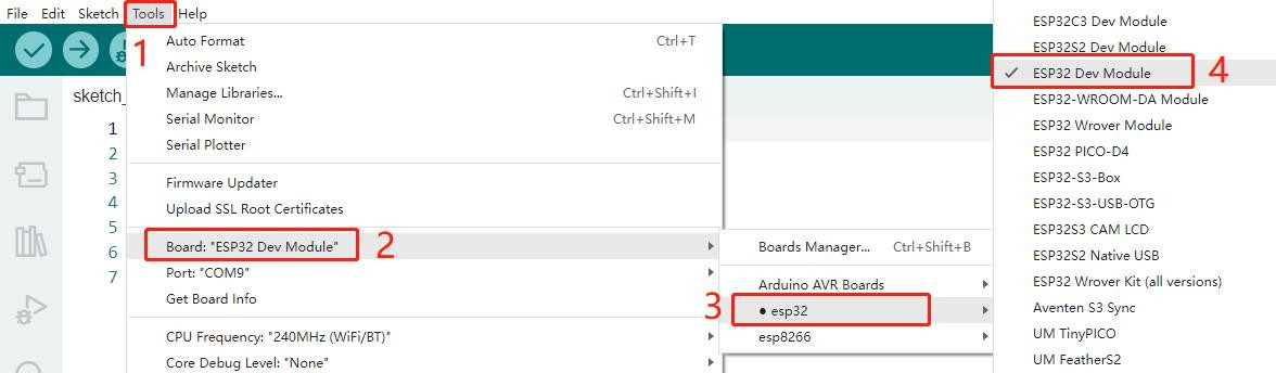
①Connect the controller board to the computer > Open Arduino IDE> Click Tools > Select ESP32> Select (ESP32 Dev Module).
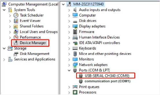
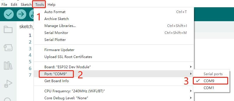
②Select the serial port (you can check the serial port number in the computer equipment manager, and then see whether the serial port number appears in the following port, because each controller board has a different COM number, please select according to the actual COM number displayed).
③Sample Code
void setup() {
    Serial.begin(115200);//Set the serial port baud rate to 115200
}
void loop() {
    Serial.println("Hello, ACEBOTT ESP32 ");//Serial port printing information
    delay(1000);
}
④Upload program
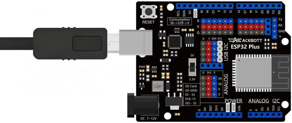
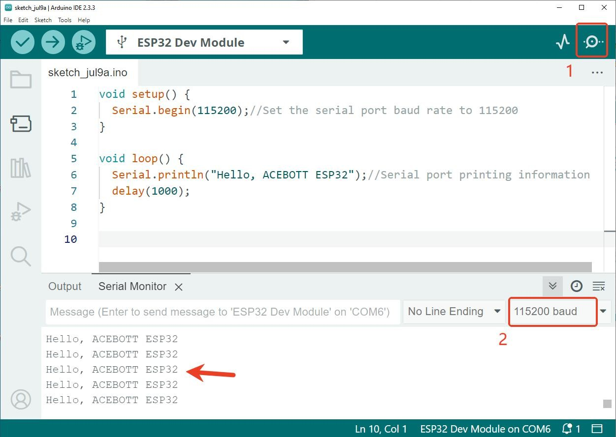
Connect ESP32 Plus controller board and computer with USB cable, select the correct controller board and port, upload the code to the ESP32 controller board, select 115200 baud rate, you can see the serial port monitor cycle print “Hello, ACEBOTT ESP32 ” effect,It means that the development environment of the controller board is installed.
Click the Upload program button:

Open the serial monitor:
ESP32 WiFi Program #
Connect the ESP32 Plus controller board to the computer with Type-B data cable, and then upload the program that can obtain nearby WiFi and display in the serial port.
(1)Sample Code
/*
When a network is found in the environment, the number and name of all nearby
networks will be obtained and displayed in the serial port, and the blue indicator will light
up.
*/
#include "WiFi.h"
void setup()
{
    Serial.begin(115200);
    pinMode(02,OUTPUT);
    //set WiFi to station mode and disconnect from an AP if it was previously connected
    WiFi.mode(WIFI_STA);
    WiFi.disconnect();
    delay(100);
    Serial.println("Setup done");
}

void loop()
{
    Serial.println("scan start");
    // WiFi.scanNetworks will return the number of networks found
    int n = WiFi.scanNetworks();
    Serial.println("scan done");
    if (n == 0) {
        Serial.println("no networks found");
    }
    else {
        Serial.print(n);
        Serial.println(" networks found");
        digitalWrite(2, HIGH);//the blue indicator lights up
        for (int i = 0; i < n; ++i) {
            //print SSID and RSSI for each network found
            Serial.print(i + 1);
            Serial.print(": ");
            Serial.print(WiFi.SSID(i));
            Serial.println((WiFi.encryptionType(i) == WIFI_AUTH_OPEN)?" ":"*");
            delay(10);
        }
    }
    Serial.println("");
    // wait a bit before scanning again
    delay(5000);
}
(2) Program effect
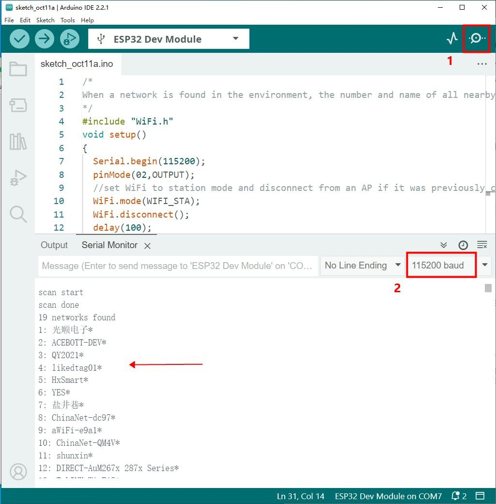
After uploading the program, open the serial monitor of the Arduino IED, you can see that the serial port circularly prints the name of the nearby WiFi, and the indicator light lights up.
Related Resources #


